Current Feedback Op-amp Testing
Big takeaway: Current feedback opamps are very particular about external component values. You must choose from the list of approved values in the datasheet or spend a lot of time hunting for an optimum value that gives you the gain and also provides stability.
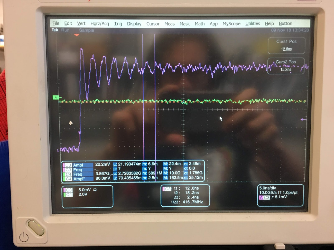
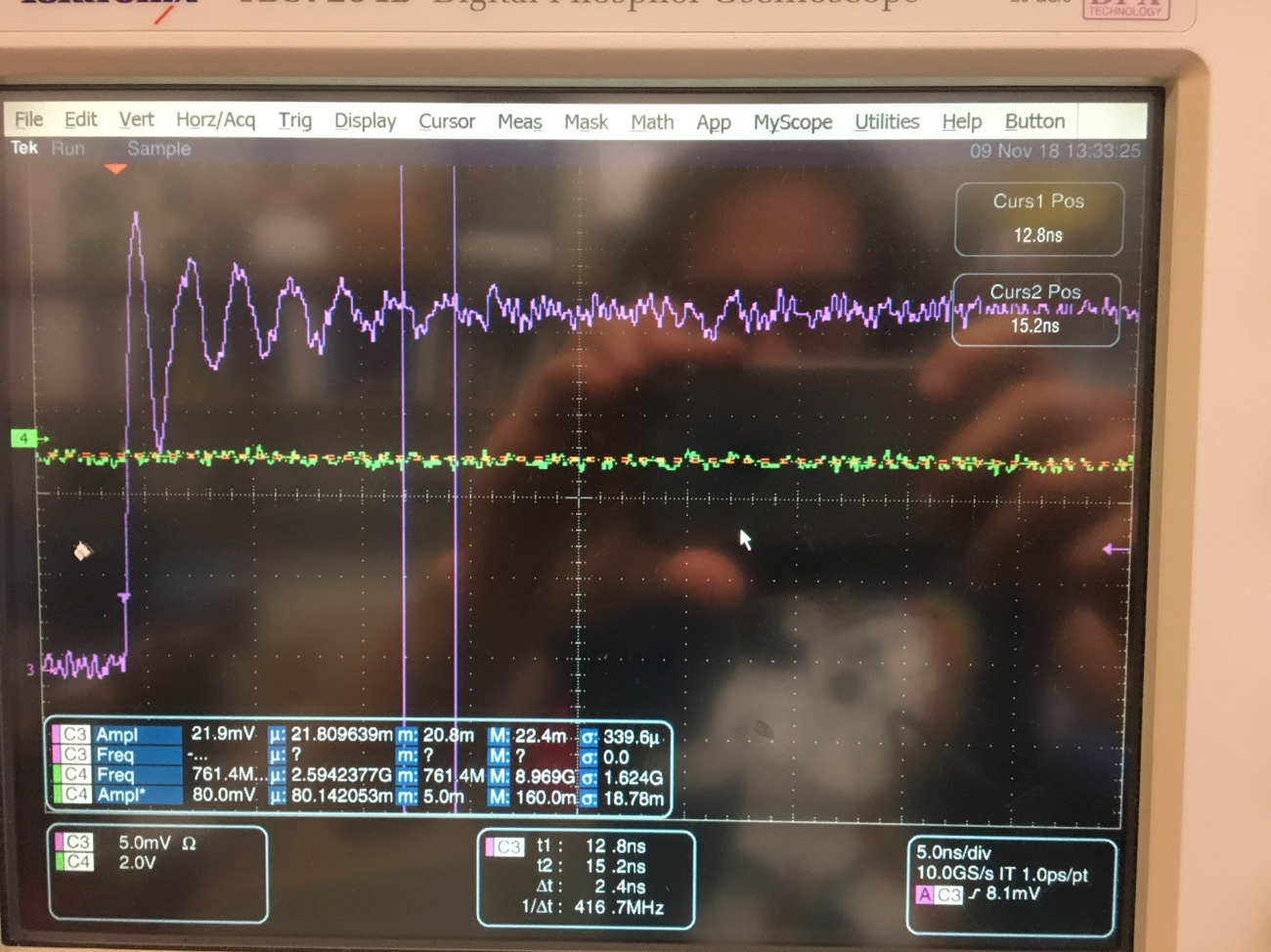
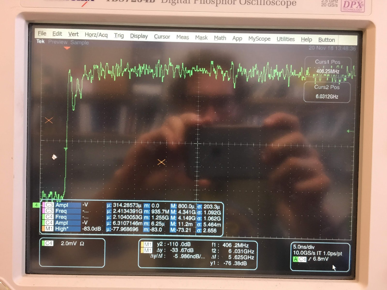
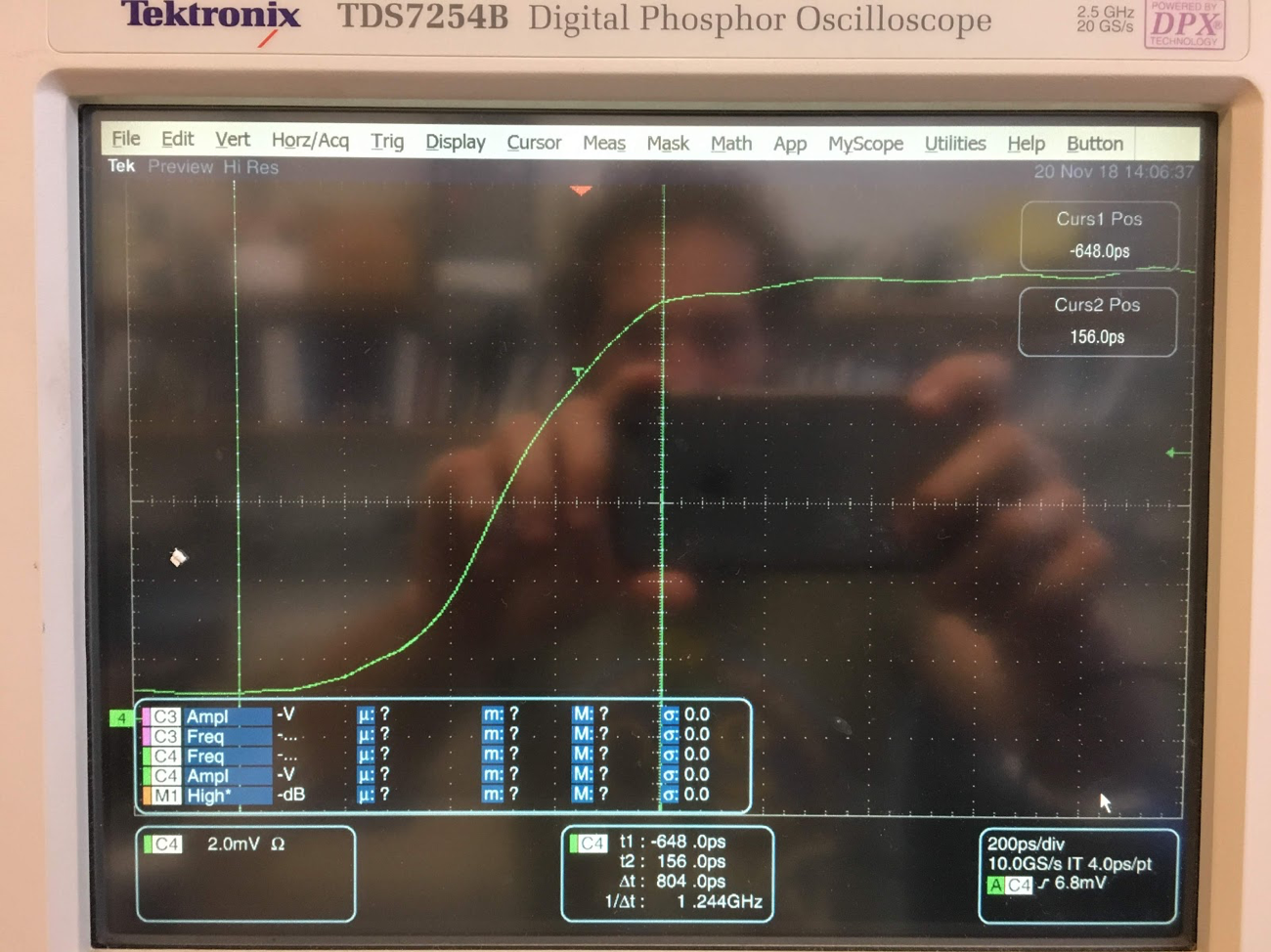
Summary: I replaced the feedback resistor elements with 510 ohm resistors for Rf and Rg. This gives a gain of two and the widest bandwidth, 1.4GHz, from the OPA695. Opamps behave much better. No more 416MHz ringing. I also removed the feedback capacitor because I read that this causes instability in the op amp.
21:1 Board Testing:
Initial results:
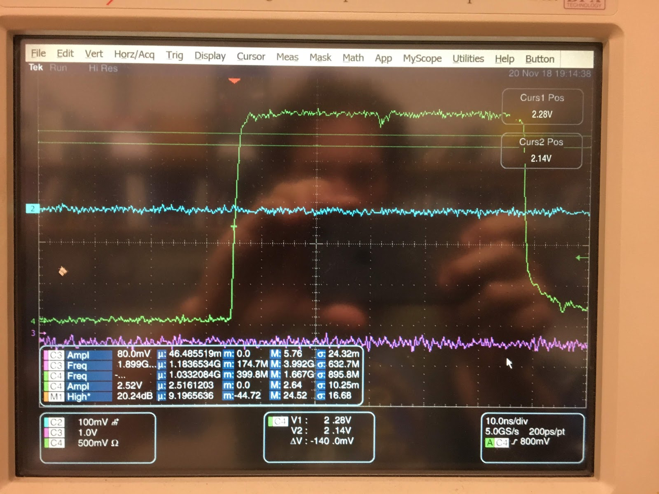
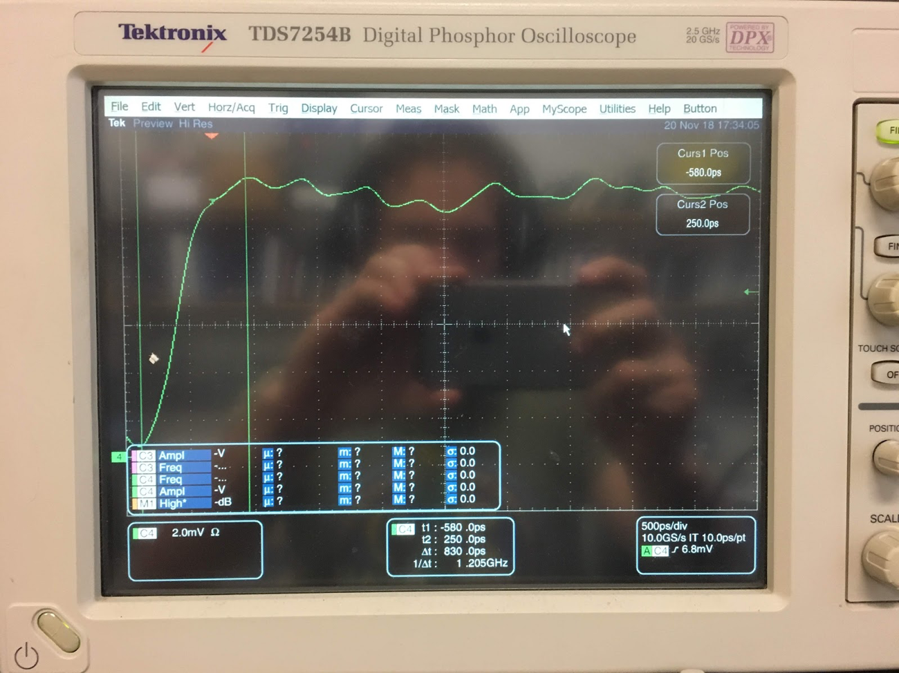
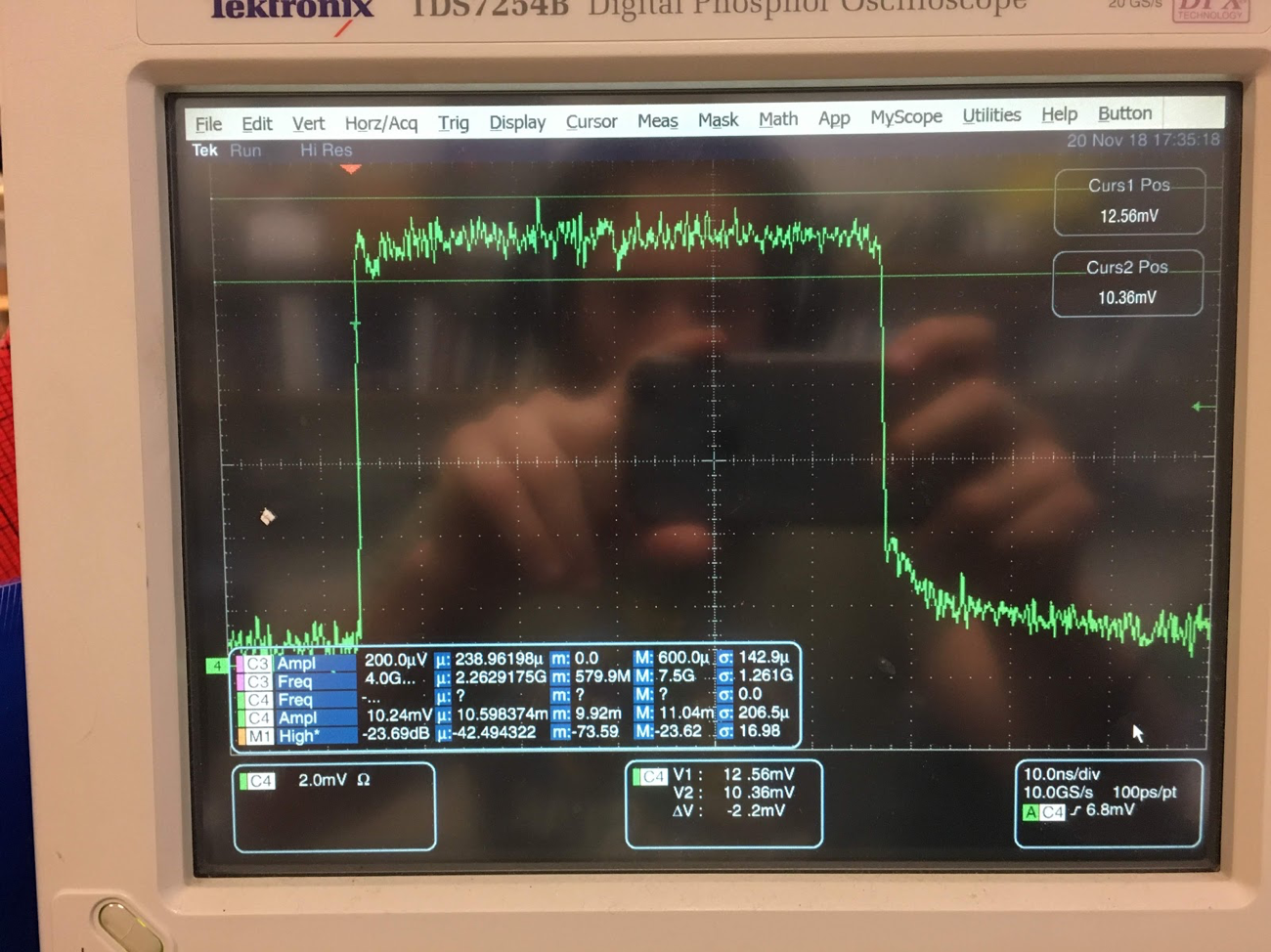
The 21:1 divider is constructed with R31 and R32. The resistor divider formed by these two resistors minimizes the effect the cable and oscilloscope parasitics on the amplifier circuit. This gives a more realistic view of the behavior of the circuit. The following two figures show the value of the 21:1 divider. With the 21:1 divider it can be seen that the behavior of the two circuits is the same. The difference seen before was due to the effect of the cable and oscilloscope loading the circuit. What this meant was the circuit design was very sensitive to parasitic loading.
Circuit Update:
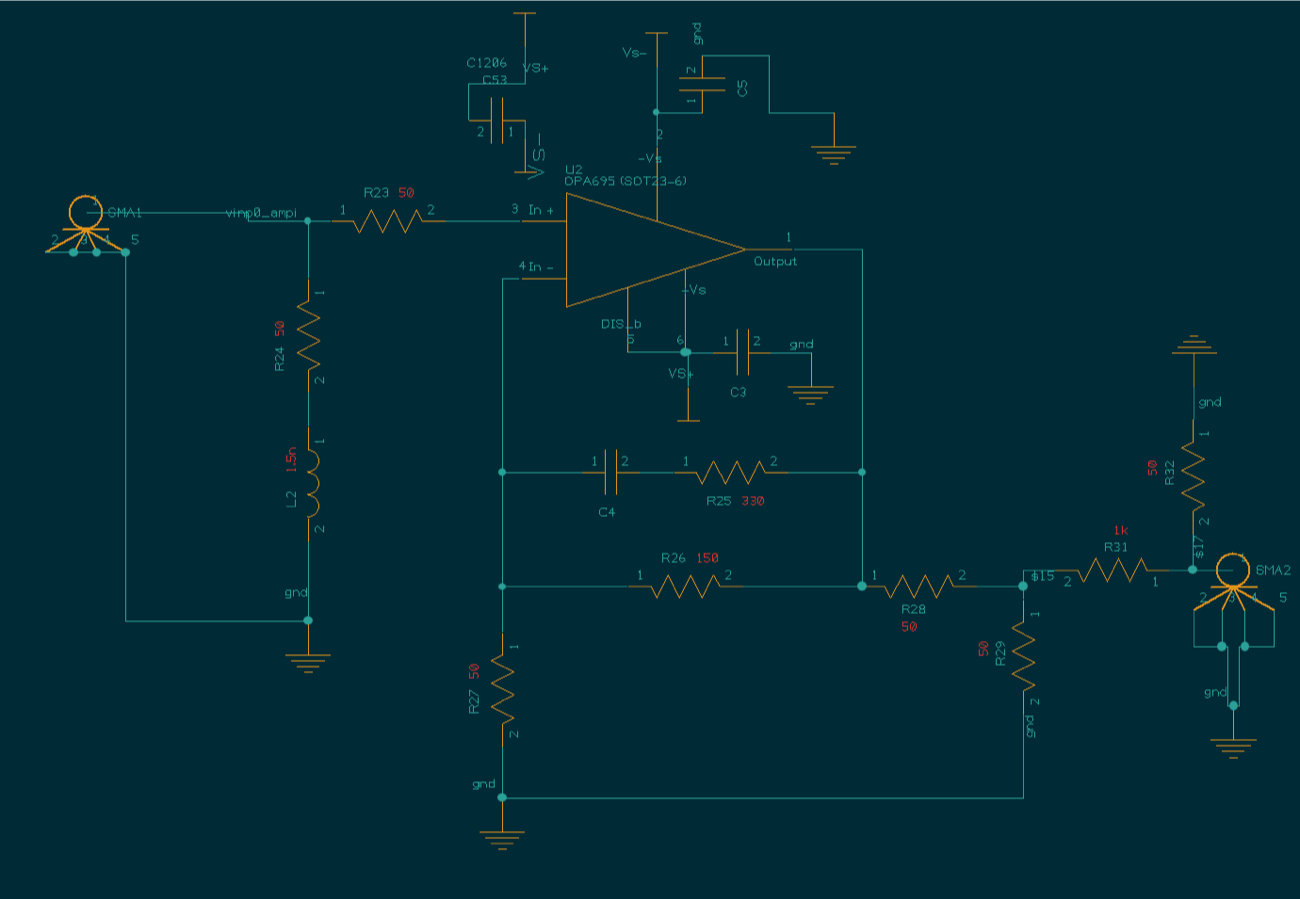
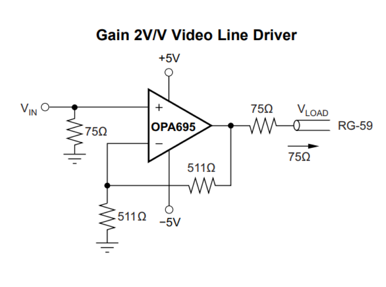
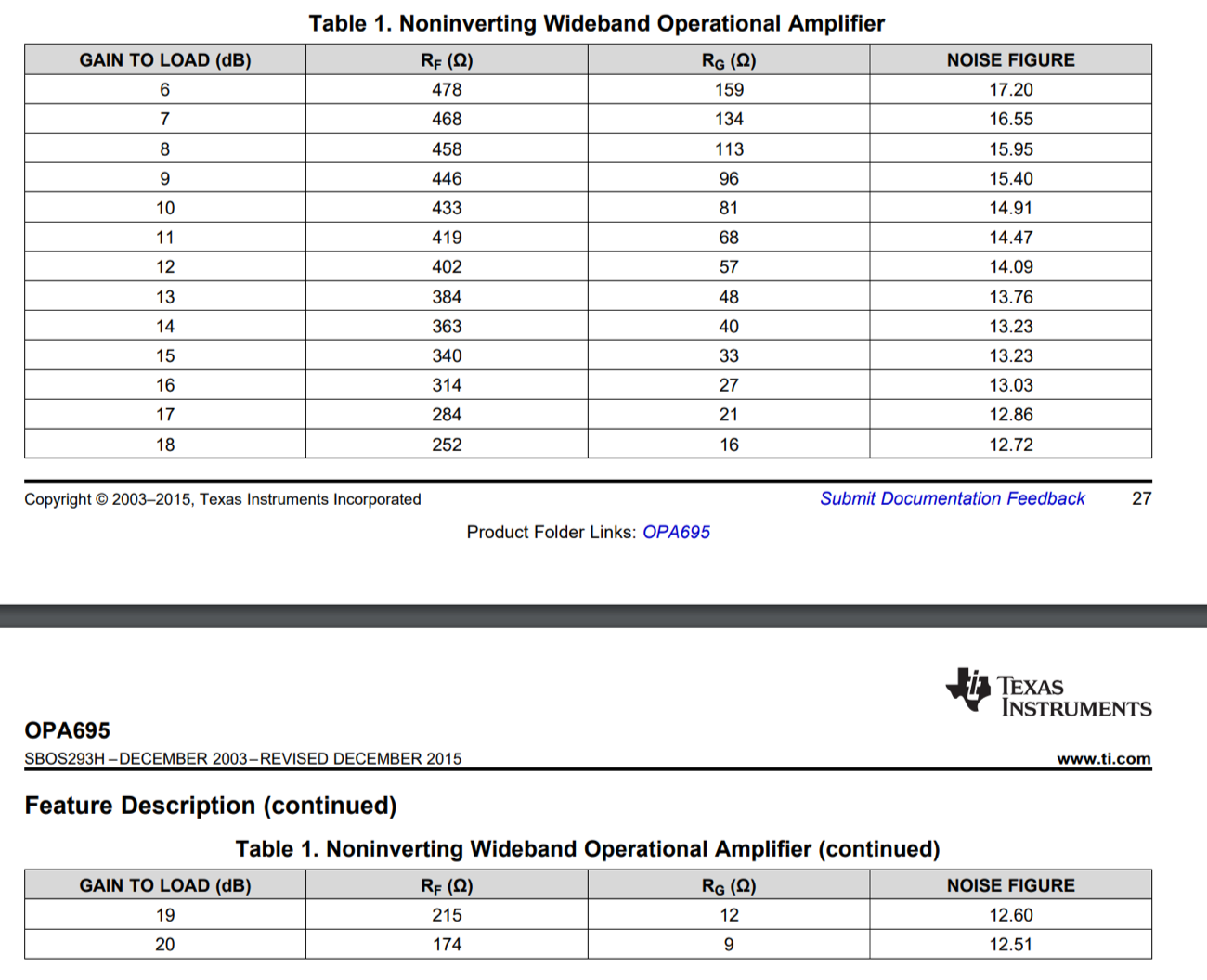
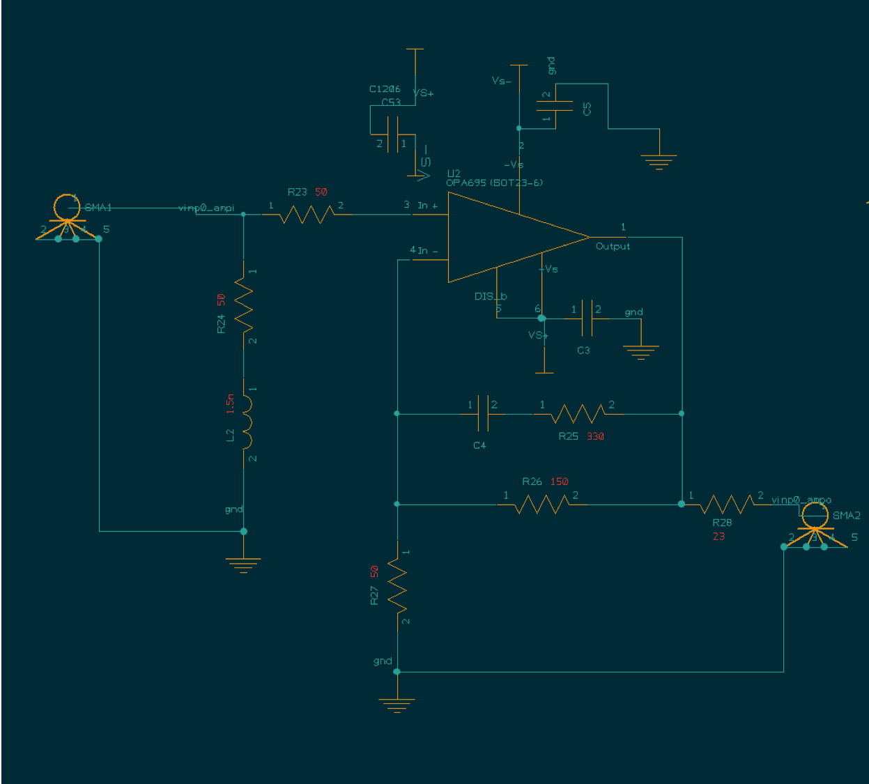
I learned from this document, http://www.ti.com/lit/an/sloa021a/sloa021a.pdf, that current feedback op amps (CFAs) are very particular about the values of the external components. The IC designers spend a lot of time looking for good values of external resistors. It is not as easy as a voltage feedback op amp. The recommended values are shown below in the table. I ended up choosing a gain of two because the OPA695 will have the widest bandwidth at this gain value, 1.4GHz. To get a gain of 2 511 ohm resistors are used for the two feedback resistors. I put 510 ohm resistors on the test board because that was the closest part available in the lab. I also read that having a capacitor in the feedback loop of a CFA is very bad for stability so I removed the capacitor.
Both of these changes drastically improved the response of the amplifier.
The resistors Rf and Rg are the 511 ohm resistors in this schematic.
Straight Post-amp Testing:
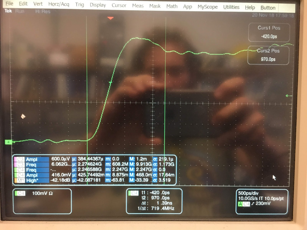
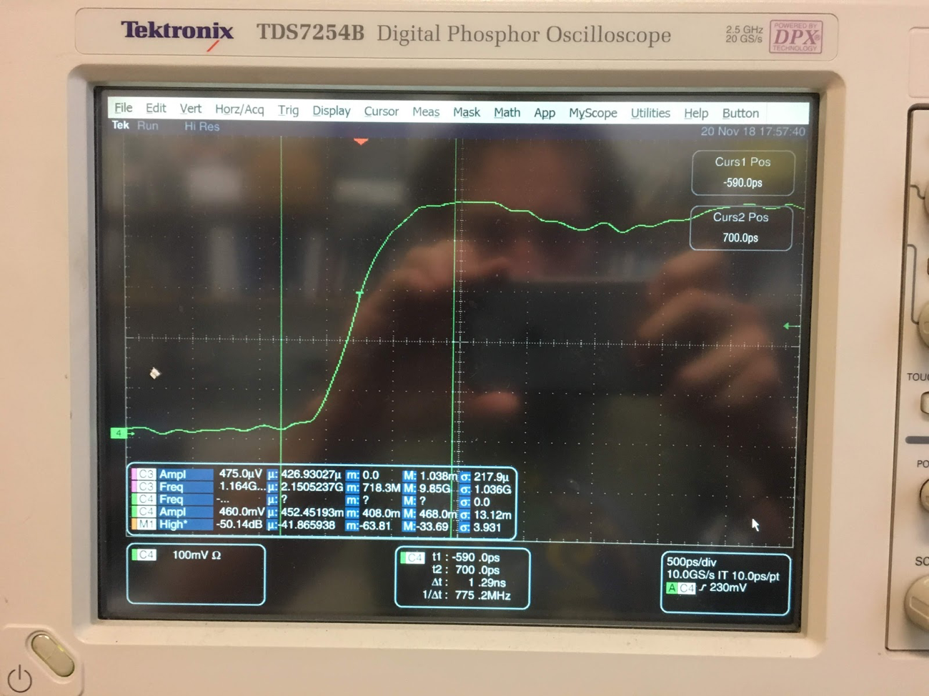
After seeing an improvement in the response of the 21:1 divider board I wanted to see what the improvement was for the straight post-amp test board.
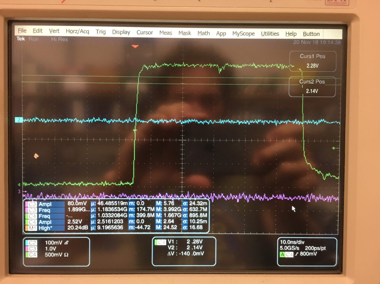
After modifying the circuit to also have a gain of 2 like I did for the 21:1 divider the response is greatly improved.
Bit Resolution:
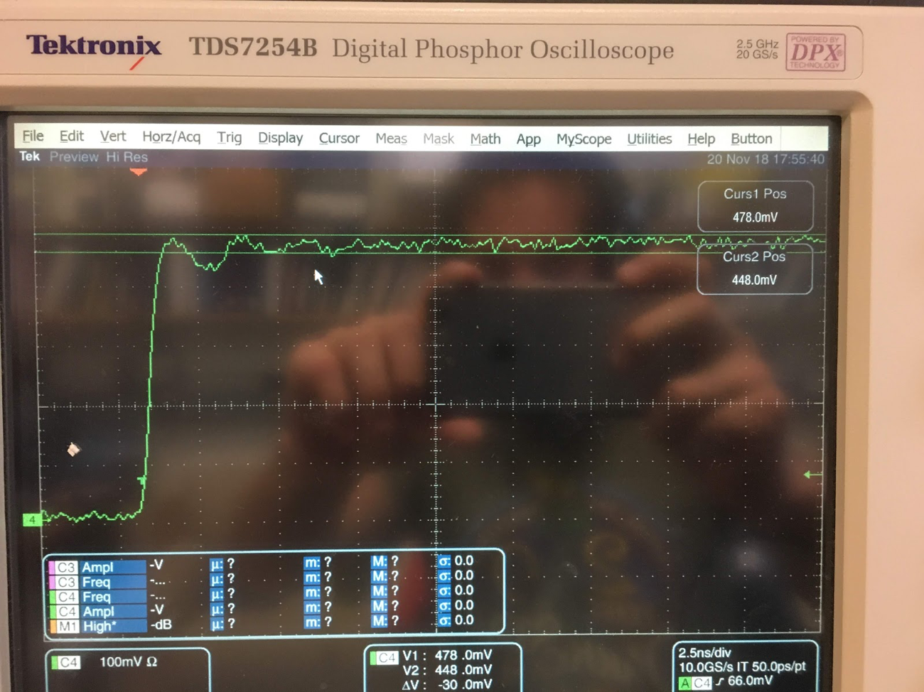
A crude measurement of bit resolution can be done by measuring the rough noise level. This measurement is shown in the following image and is ~30mV.
To get the amount of bits lost first the LSB must be calculated:
$$\frac{Max voltage}{2^{Num Bits}} = \frac{voltage}{bit}$$
| # | Bits | Max Voltage | Volt / LSB |
|---|---|---|---|
| 1 | 16 | 5 | 7.62939E-05 |
Using our measured noise margin of 42mV the number of lost numbers can be calculated. \(\frac{0.042}{7.62939*10^{-5}} = 550\). Taking the log base 2 of 550 gives us the number of bits lost: 9.104605043. And subtracting this value from 16 bits gives us the remaining bits we have: 6.895394957. So 6 or 7 bits. I also measured the signal generator directly and it had the same amount of noise. So, the noise level seems to be inherent in the scope or signal generator.
5V operation:
5V operation was accomplished with the power supplies set to +-6.5. The scope shows 2.5 volts because of the resistor divider on the output of the post amp.
