16 Bit DAC FMC Card
We required a higher resolution and faster Digital-toAnalog Converter (DAC) for our IRLED micro-display screen. The DAC in this program is responsible for setting the brightness of the IRLED pixel. A little overview diagram of the IRLED micro-display system would help understand the architecture. Below is a block diagram of the different components.
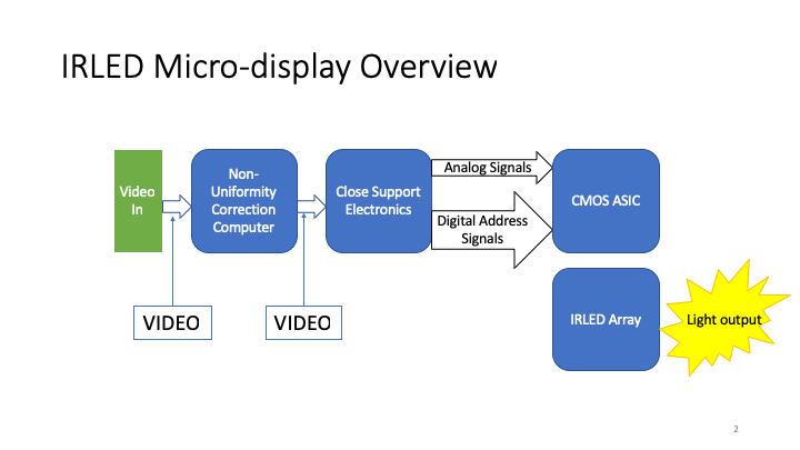
The information input for the system starts on the left of this diagram. Input video data comes in and is pre-distorted to account for individual pixel non-uniformity. We call this a Non-uniformity or NUC. The NUC’ed video is sent onto the Close Support Electronics (CSE). The CSE contains an FPGA that is responsible for converting the input video data format into the frame format used to draw imagery with CMOS ASIC. Out of the FPGA comes digital address signals and digital brightness values for each pixel. The job of the DAC board is to convert the 16 bit digital numbers from the FPGA into analog voltages. The analog voltages are then amplified using a several stage amplifier chain to the correct voltages for the ASIC.
Due to the high frame rates (400Hz to 1KHz), and high pixel resolution (512×512 to 2048×2048) required by the application of the IRLED micro-display the DAC must settle to the new value quickly. Commercially available high end DAC systems are typically setup for Radio Frequency (RF) applications because that is typically the use case for these devices. For our purposes we required time domain operation and preservation of DC information. This ultimately required an in-house design of a new DAC board. A picture of the end product of this in-house design effort is shown below.
We required a higher resolution and faster Digital-toAnalog Converter (DAC) for our IRLED micro-display screen. The DAC in this program is responsible for setting the brightness of the IRLED pixel. A little overview diagram of the IRLED micro-display system would help understand the architecture. Below is a block diagram of the different components.
irled_micro_display_overview
The information input for the system starts on the left of this diagram. Input video data comes in and is pre-distorted to account for individual pixel non-uniformity. We call this a Non-uniformity or NUC. The NUC’ed video is sent onto the Close Support Electronics (CSE). The CSE contains an FPGA that is responsible for converting the input video data format into the frame format used to draw imagery with CMOS ASIC. Out of the FPGA comes digital address signals and digital brightness values for each pixel. The job of the DAC board is to convert the 16 bit digital numbers from the FPGA into analog voltages. The analog voltages are then amplified using a several stage amplifier chain to the correct voltages for the ASIC.
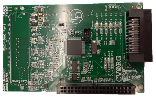
Due to the high frame rates (400Hz to 1KHz), and high pixel resolution (512×512 to 2048×2048) required by the application of the IRLED micro-display the DAC must settle to the new value quickly. Commercially available high end DAC systems are typically setup for Radio Frequency (RF) applications because that is typically the use case for these devices. For our purposes we required time domain operation and preservation of DC information. This ultimately required an in-house design of a new DAC board. A picture of the end product of this in-house design effort is shown below.
DAC_image
At the top is a silkscreen rectangle that outlines the FMC connector. The FMC connector is used to attach this PCB to the FPGA board. FMC is convenient because it is a high density connector that maintains good signal integrity. Moving to the right is a sea of passive components that are supporting the two DACs on the other side of the card, terminating signal lines, and providing capacitance to power supplies.
The micro controller is the first IC visible on the board when moving from the FMC connector to the right. The micro controller is responsible for programming the DAC when testing the board without the FPGA, monitoring voltage levels of power supply lines, operating the feedback Analog to Digital Converter (ADC) for tuning in DAC parameters and setting LED light displays.
Moving to the right past the micro controller are the LED lights and the crystal for the micro controller. There are also two headers. One is a 100 mil pitch header and the other is a right angle header. The 100 mil pitch header is used to connect the DAC output to an amplifier card PCB, and the right angle header has several test signals routed to it for ease of troubleshooting.
Major Components
Digital to Analog Converters
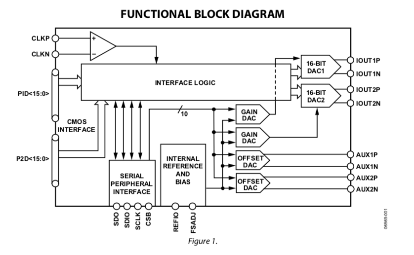
The DACs used in this project are the AD9747s from Analog Devices. These DACs were chosen because they support 16 bits and fast enough sample rate (250 MSPS) for the application. A block diagram of the AD9747 is shown below. In each AD9747 part there are two DACs.
Microcontroller
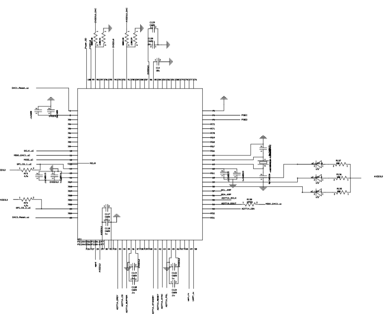
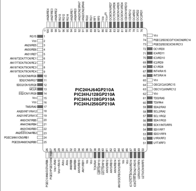
The micro controller used in this project is a 16 bit PIC24. This micro controller was chosen because other in-house projects use this micro controller. This alleviated the need to maintain two tool chain and build environments for development work. If we were a larger organization I probably would have chosen a different micro controller. The PIC24HJ256GP210A- version of the micro controller was used in this project. The pinout for this micro controller is shown below.
Schematic
Digital to Analog Converter
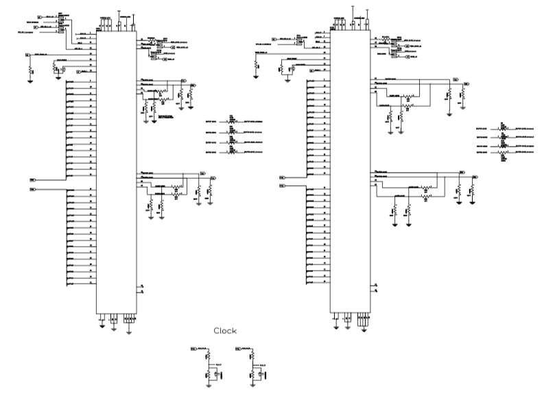
The schematic for both DACs are shown below. The data signals from the FPGA come in from the left and are shown as a large bus that looks like the wires are shorted together. On the right are the two outputs from the DACs. The DACs have gain and offset adjustment secondary DACs to improve the performance of the main DACs. The resistor networks on the right are used to properly connect these adjustment DACs to the main DACs.
Micro-Controller
The schematic for the micro-controller is shown below. The micro-controller has an SPI connection to the FPGA in order to control the micro-controller and pass it new configuration parameters for the DACs. As well as any other required general communications. On the right the micro-controller is connected to the output LEDs for signaling board status and events.
